Fully assembled mechanical fish.
Mechanical Fish Lab
Why is this important?
Biological propulsion systems introduce a variety of behaviors not found in typical mechanical propulsion systems. The most prevalent of these is unsteady operation of the propulsion system. That is, biological propulsion systems tend to vary or cycle over time instead of using the steady unchanging operation typical of mechanical propulsion systems. In this activity, you will investigate an unsteady, mechanical flapping fin propulsion system with fin motion similar to thunniform or carangiform swimmers (although the shape of the fin and the resulting flow is more like a trout).
What do I need?
Tamiya Robocraft Mechanical Blowfish [Assembly required. Materials needed for assembly: small Phillips-head screwdriver, hobby knife.]
3 AA batteries
Scotch tape
Scissors
Tank or tub of water (A 3 ft x 1 ft (1 m x 30 cm) tank or wading pool more than 6 in (15 cm) deep will work fine)
Measuring tape
Stopwatch
How do I do it?
Assemble the mechanical blowfish according to the directions enclosed within the box. When you are finished the fish should look like the fish in the picture below.
Fully assembled mechanical fish.
The kit comes with a battery holder that only holds one battery. Increasing the voltage applied to the motor will increase the speed of the motor, thereby increasing the flapping frequency of the fin. To increase the voltage, you will need to connect the multiple batteries to the motor. Do this using the 2 and 3 AA battery holders in the materials list. For now just prepare them for installation in the blowfish (which may require cutting and stripping wires for the holders).
Procedure:
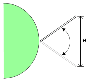
For steps 4 and 5 record your results in a table like the one shown below.
| 1 battery | 2 batteries | 3 batteries | |
|---|---|---|---|
| Small fin | V: f: H: |
V: f: H: |
V: f: H: |
| Large fin | V: f: H: |
V: f: H: |
V: f: H: |
Make a plot of V vs. f for each fin size. Include the plots for both fin sizes on the same graph so they can be compared. Plot f on the horizontal axis since it is the dependent variable.
What did you observe?
What happens to V as f is increased? Why? Was the long fin or the short fin more effective?
Compute fH/V for the cases you studied and plot V vs. fH/V. Based on the values of fH/V, which configuration is probably most efficient? [Hint: Review the section on undulatory swimming.]
Want to do more?
Buy a thick piece of plastic (a plastic cover for an old 3-ring binder also works) and cut out different fin shapes. Attach your fin to the blowfish and see how well it swims. Can you improve the swimming speed over the current fin design?