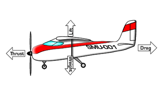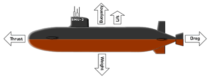

Drag
The reason propulsion is necessary follows directly from Newton’s second law. In order to start an object moving, a thrust force is needed to generate an unbalanced force on the object. The lower the mass of the object, the less thrust is required to achieve a given initial acceleration. Once the object is moving, however, its motion is resisted by a drag force, so without a continual thrust force, the object will decelerate and eventually come to rest.
 |
 |
During cruise operation, the objective of the thrust force is to balance the drag force (FT = FD) so that the net force on the object is zero and it moves at a constant velocity (zero acceleration). The lower the drag on an object, the lower the thrust force required for cruise.
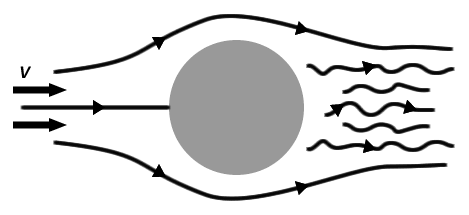
Drag: To appreciate the job of thrust during cruise, it is helpful to know a little bit about drag. For an object cruising through a fluid at a steady speed V (not accelerating or decelerating), it is equivalent to consider the flow from the point of view of the object with the fluid approaching at a speed V. This situation is illustrated below for flow around a ball.

Flow lines around a ball.
With the flow approaching at a speed V, drag is the force required to hold the object in place and is determined by

where ρ is the fluid density, A is a "reference" area of the object, V is the fluid speed relative to the object, and CD is known as the drag coefficient. The reference area A is typically the cross-sectional or frontal area of the object (pR2 for a sphere), but may also be the surface area (wetted area) or other representative area describing the object. Notice that according to this formula, a higher cruise speed V requires a larger thrust force to counteract FD.
The drag coefficient is a parameter that depends on the particular situation, including the geometry of the moving object and fluid properties such as viscosity. Typically CD for a given situation is measured experimentally, but in certain special cases it may be computed from a formula. A large drag coefficient means that the object creates a lot more drag (is harder to propel) than a similarly sized object with a low drag coefficient. A table of CD for different vehicles is provided below.
Shape |
Reference Area |
Drag Coefficient, CD |
 Six-car passenger train. |
Frontal Area |
1.8 |
Bikes

Upright commuter

Racing

Drafting

Streamlined
|
A = 5.5 ft2
A = 3.9 ft2
A = 3.9 ft2
A = 5.0 ft2 |
1.1
0.88
0.50
0.12 |
|
Tractor-trailer trucks

Standard

With fairing

With fairing and gap seal
|
Frontal area
Frontal Area
Frontal Area
|
0.96
0.76
0.70
|
|
Animals

Dolphin

Bird
|
Wetted area
Frontal area
|
0.0036
0.4
|
|
Planes

Subsonic Transport Aircraft

Supersonic Fighter, M=2.5

Streamlined body (e.g. submarine)
|
Frontal area
Frontal area
Frontal area
|
0.012
0.016
0.04
|
While the details of how CD is determined are beyond the present discussion, it is worth noting how CD depends on two key factors: geometry and viscosity.
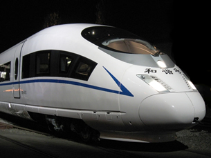
Geometry: CD is strongly affected by the geometry of the object. In particular, objects with very blunt or “boxy” geometries have large drag coefficients. This is due to high fluid pressure on the front of the object and low fluid pressure on the back of the object. Conversely, objects that are streamlined or fusiform, have low drag coefficients. Because of the dependence on geometry, this effect is known as form drag. To avoid large thrust force, it is desirable to minimize form drag by using a streamlined fuselage.
 A streamlined bullet train. CRH3 Velaro bullet train in China. |
 A blunt, boxy shaped car. Scion xB |

|
Example Problem: Golf Ball Drop |
