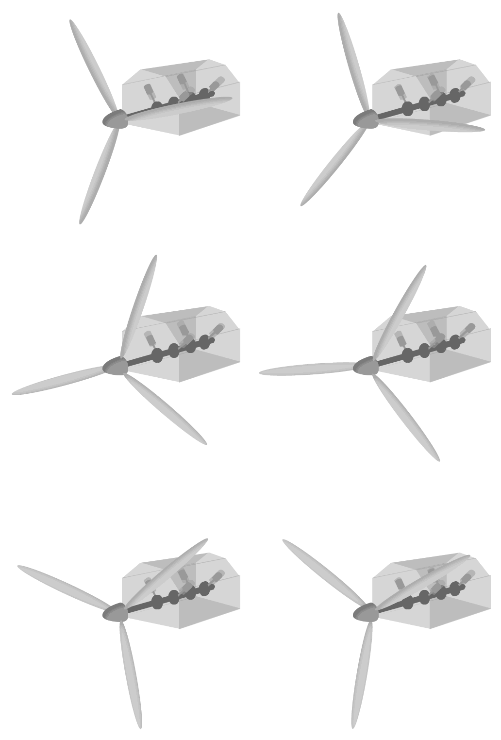
Propellers
Propellers are used on boats, submarines, and small aircraft. Propellers are simple, revolving hubs with blades placed evenly along the edges (usually 2 to 4 blades on a propeller, but more are possible). A mechanical engine attached to the propeller converts fuel or other stored energy into mechanical power which turns the propeller at a high rate of speed.

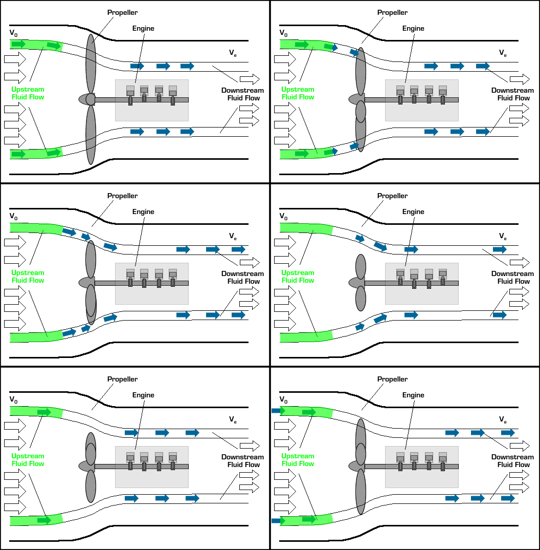
In small aircraft, the propeller is normally powered by a piston engine as shown above. In larger vessels like nuclear submarines, the propeller may be powered by a nuclear power plant. The basic operation of a propeller propulsion system is described in the interactive animation below. Use the arrows to step through descriptions of the different components.
 |
|
 |
|
 |
 |
The design of a propeller is crucial for this system to generate thrust efficiently. A propeller may be thought of as a spinning wing. Wings have a very special shape in order to direct the flow around them in a specific way.
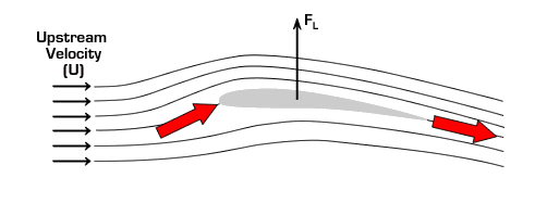
In the figure above it can be seen that near the back a wing has a slightly steeper slope on the top as compared to the bottom. As a result, the fluid flowing over the wing tends to flow down and away from the wing as it passes the end or "trailing edge" of the wing. Near the front of the wing, the curvature of the top of the wing adds to this effect because the flow must curve up as it approaches the wing in order to flow smoothly over the hump on the top of the wing. The net effect is a change in flow direction from upward to downward by the wing. Because the flow is accelerated down (the direction of the fluid velocity is changed to the downward direction), Newton’s Third Law requires there be an upward reaction force on the wing. The process is analogous to the force required to bounce a ball on the ground. Both the process of catching the ball as it bounces up to your hand and throwing it back down to the ground exert a vertical force on your hand because your hand must change the motion of the ball from upward to downward.
The vertical force acting on the wing is called lift and it is what keeps airplanes aloft. If the angle of the wing relative to the oncoming flow (angle of attack, α) is increased, the downward acceleration of the flow is enhanced and lift is increased (as long as α is not too large).
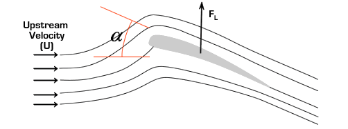
In general, the lift force can be computed from the equation

where ρ is the fluid density, U is the upstream flow speed, and A is the wing area. CL is called the lift coefficient and it depends on the wing geometry and α.
Now envision the above scenario rotated 90° counter clockwise so that the top of the wing is facing forward. The force on the wing is now pointed forward, creating thrust instead of lift. In this orientation, we call the wing a propeller "blade".
Just rotating the wing 90° isn't enough to turn lift into thrust. The propeller blade must also be spun around its axis. Spinning the blade induces the fluid to flow over the blade in a manner similar to the flow over a wing, but rotated 90° to generate thrust. This is best described graphically. In the center of the figure below is a side view of a spinning propeller blade. Only a slice of the blade is shown so you can see the wing-like shape of the propeller blade moving through the oncoming flow. For future reference, let's say the chosen slice of the blade is a distance r from the hub (see the picture on the left in the figure). On the right of the figure is the flow seen from the point of view of someone sitting on the propeller blade (relative motion is reviewed here). In this view, the flow moves past the propeller blade in a manner similar to that illustrated for the wing above. Notice that the angle of the oncoming flow (α) is determined by (a) the speed of the aircraft (V0), and (b) the vertical speed of the propeller, namely, W = 2πnr where n is the rotation rate of the propeller in revolutions per minute (rpm). As with the wing, the propeller blade accelerates the oncoming flow away from it, generating force ( ) in a direction perpendicular to the oncoming flown as shown. (Here we call the "lift" force generated by the blade
  instead of FL because
  is not perpendicular to the motion of the airplane as is the case for lift on a wing.) The horizontal component of
  points forward, giving the desired thrust (FT). (Click here to review vector components.) Notice also that there is a vertical force component that resists the motion of the blade and must be overcome by the motor that spins the blade. That is, work must be done by the motor to generate thrust. There is also a "drag" force on the blade parallel to the oncoming flow (F||). This parallel force tends to reduce thrust and increase the work required from the motor, but for a well-designed propeller, this effect is small.
Front View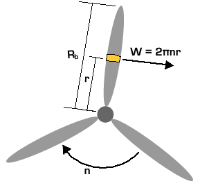 |
Side View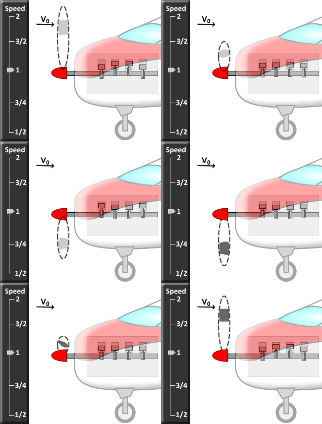
|
Sitting on Blade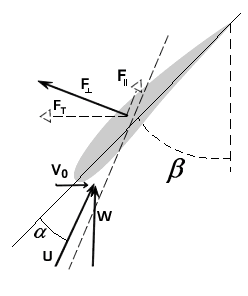 |
Thrust can be increased by increasing  , which can in turn be increased by increasing the oncoming flow speed (U) and α in the same way that lift on a wing is increased. Since U is the vector sum (addition) of V0 and W, both U and α can be increased by increasing W, which increases with propeller rotation rate n (click on the different speed levels to see how changing n changes the forces on the propeller blade). Thus, simply revving the engine to make the propeller spin faster will generate more thrust. Unfortunately, increasing W also increases the drag that resists propeller motion that requires more power from the motor to spin the propeller. The net effect is that the propulsive efficiency of the propeller tends to decrease as the propeller is spun faster for a given flight speed V0. The optimum condition is for α to be just large enough to give the thrust required at the given W, but no larger. Since W increases with distance from the hub for a given n (W = 2πnr), well-designed propellers have a β that decreases with r for optimal performance.
From the point of view of the thrust equation introduced in the Principles section,  for a propeller since the downstream air pressure is the same as the ambient air pressure. At the condition of optimal propeller efficiency, α is small all along the propeller blade, so the air flow is not deflected much by the propeller blade and Ve - V0 is small. (Recall that small Ve - V0 corresponds to high propulsive efficiency because there is less kinetic energy left behind (wasted).) In order to generate sufficient thrust to propel the vehicle, therefore,
  must be large. The mass flow rate through the propeller,
  , depends primarily on the area swept out by the propeller blades (calculated as πRb2 where Rb is the length of a propeller blade) and n. Most propellers use relatively large Rb and moderate n to achieve the required thrust. If either Rb or n are increased too much, however, the speed of the blade tips can become too high causing shockwaves to form on propeller blades in air or cavitation to occur on underwater propellers. The limits on Ve - V0, Rb, and n for efficient operation limit propellers to relatively low flight speed applications compared to jet engines. For a given propeller, propulsive efficiency drops sharply at high V0. At lower V0, however, propellers are very efficient. Well-designed propellers can achieve propulsive efficiencies in the range of 80-90% at design vehicle velocities.
Internal Combustion Engines:
With propeller-based propulsion, the propeller is only part of the story. An engine or motor is still required to turn the propeller. A common engine used in propeller driven boats and small aircraft is an internal combustion (IC) engine. As noted above, other options are available, but because IC engines are quite common in this application, their basic operation as part of a propulsion system will be described here. Another popular method using a turbojet engine (combining a propeller and a turbojet to give a turboprop engine) will be described later.
The main components of an IC engine are shown in the animation below. In an IC engine, energy is extracted from the fuel by combining it with air and burning it in isolated, internal chambers containing pistons. After combustion, the high temperature gas expands, pushing the piston down and converting thermal energy into mechanical work. The pistons are connected to a crankshaft which converts linear piston motion into rotational motion. The crankshaft may be connected directly to a propeller or via a gearbox (to rotate the propeller at a different speed from the crankshaft). An overview of the operation of an IC engine is provided in the interactive animation below. Click on the component names to obtain the corresponding component description.
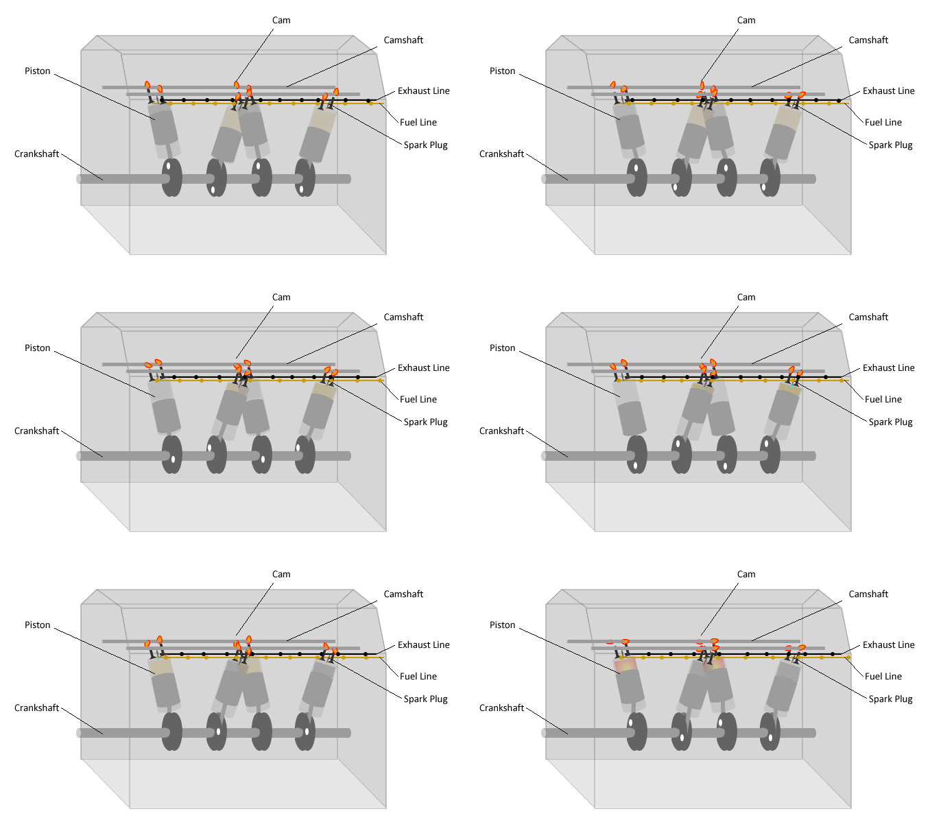
Click on the labels above for a more detailed explanation of each part. |
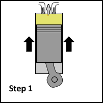
Inside the piston cylinders a specific sequence of events is executed in order to convert the chemical fuel energy into mechanical power. The most common sequence used in moderate to large IC engines is the 4-stroke cycle. The steps (or "strokes") in this sequence are described in the interactive diagram below. Use the arrows to step through descriptions of the events in each stroke.
|
|

|
|
 |
 |
Increasing the amount of fuel injected (stepping on the throttle) increases the power output of the engine, which may be manifest as either an increase in torque or rotation rate of the crankshaft. As the temperature of the gas in the cylinder after combustion (Step 2) increases, the engine converts a larger fraction of the fuel energy into mechanical power (thermal efficiency is increased). A key factor contributing to the temperature of the gas in Step 2 is the compression ratio, defined as the ratio of the cylinder volume when the piston is at the bottom (Step 4) to the cylinder volume when the piston is at the top (Step 1). A larger compression ratio leads to a higher temperature when the piston reaches the top in Step 1 and hence, a higher temperature after the fuel is burned. Thus, increasing compression ratio tends to increase the thermal efficiency of IC engines.
For gasoline engines, if the compression ratio is too large, the fuel-air mixture will start to ignite before it reaches the top, leading to knocking, engine damage, and lower efficiency. As a result, compression ratios in gasoline engines are limited. Diesel engines compress only air, however, so the gas cannot ignite during compression and quite large compression ratios are possible in diesel engines. As a result, thermal efficiencies tend to be higher in diesel engines. Typical thermal efficiencies are 25-35% for gasoline engines and 35-40% for diesel engines.
