Grating-Outcoupled Surface-Emitting Lasers
- Two-Wavelength GSE lasers
- Integration of GSE lasers with Heterostructure Bipolar Transistors
- Four-Wavelength GSE lasers
- High-Speed Phase-Shift Modulators for GSE lasers
- Quantum Well Intermixing
- High Power Grating-Outcoupled Surface-Emitting Lasers
Grating-Assisted Directional Couplers
 |
Southern Methodist University |
| School of Engineering | |
| Link to Dallas LEOS Section | Department of Electrical Engineering |
Two-Wavelength Cross-Grating GSE Lasers
A sketch of a two-wavelength "crossed-grating"
GSE laser is shown in Fig. 7a and SEM micrographs of a partially
processed device is shown in Figs. 7b,c.
This device consists of two independent GSE lasers oriented perpendicular
to each other. Each GSE laser has different DBR and outcoupler
grating periods. To achieve an emission wavelength l of 1310 nm requires a DBR period
L of about 198.5 nm (L = l/(2 neff)), where neff is the effective index
of the optical mode in the laser. To change the emission wavelength
to 1305 nm requires a grating period for the second laser of 197.7
nm. The second order outcoupler gratings have twice the period
of the DBR gratings. The holographic lithography process for grating
fabrication allows a grating period accuracy and adjustment of
~ 0.1 nm.
Fabricating the two-gratings of the outcoupler at right
angles to each other (see Fig. 7c) with nearly the same period
results in an ¡°effective grating¡¹ at an
angle of about 45 degrees (see Fig. 7c). This effective grating
can act as a distributed Bragg deflector (DBD) and diffract incident
light at an angle of 90 degrees, which could cause cross talk
in the proposed device. However, for TE polarization, the theoretical
diffraction efficiency for a 45-degree DBD is zero [9]. Initial
experimental work verified that perpendicular arrays of TE polarized
GSE lasers designed with a large DBD region (80 µm x 80
µm) intended for DBD coupling of perpendicular laser arrays
showed little if any coupling [10] and verified that perpendicular
GSE lasers can operate efficiently while sharing the same outcoupling
aperture.
The light-current (L-I) curves for each
of two cross-grating lasers are shown in Fig. 8. The single-frequency
spectrum of each laser, measured by coupling the output into a
single fiber positioned above the outcoupler (Fig. 7c), is shown
in Fig. 9a and indicates that the wavelengths are separated by
~ 9 nm (the target spacing was 10 nm). The far-field radiation
pattern from the common outcoupler (Fig. 7c) with both lasers
operating is shown in Fig. 9b.
The epitaxial
material used for this concept demonstration had compressively
strained quantum wells so that the lasers operated with TE polarization
to minimize/eliminate cross talk of the two lasers. Initial measurements
do not indicate optical cross talk.
|
(a) |
(b) |
(c) |


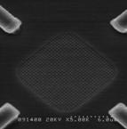
Fig. 7. a) A two-wavelength crossed-grating GSE laser emitting independently from the same aperture. b) SEM micrograph of a two-wavelength crossed-grating GSE laser; c) SEM micrograph close-up of the cross-grating aperture.
|
(a) |
(b) |


Fig. 8. Light current curves of each independent laser of a 2 wavelength cross-grating laser. a) LI corresponding to the 1330 nm GSE; and b) LI corresponding to the 1321 nm GSE.
|
(a) |
(b) |

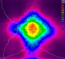
Fig. 9. a) Single frequency spectrum of each GSE laser element in the cross-grating laser array; b) Radiation pattern of the cross-grating GSE laser array with both laser elements